Vintage DC-coupled Audio Amplifiers do often make a loud "POP!" in the speakes when power is applied.
On my Revox A78 I decided to solve this problem by design a speaker-delay circuit that will disconnect the speakers while the DC-output stabilises.
I ended up with this schematic:
 Since the circuit has to be fast reacting when the amplifier is turned on-off, the circuit has to be coupled to the AC-part (secondary winding) of the mains transformer.
D4 and C2 will make DC-voltage. The ripple is quite high but sufficient to keep the relay switched without buzzing, but fast reacting when the AC-voltage suddenly disappears (when the amplifier is turned off).
No voltage regulation is used, but R1 is used to limit the DC-voltage to +24VDC when the relay is loading the circuit.
The relay is placed outside the circuit. Thats makes it easy to use different footprint and near the speaker connections. D1 is a "Flywheel-diode" to avoid damaging some nearby components sensitive to high voltage when the current flow is interrupted.
The current flow is controlled by a darlington configuration. The high current gain will make the switching more "consequent" when C1 is charged up by the current, limited by R4. R5 is used to limit the base current though the transistors. The zener diode D3 is used to "extend" the delay time (insted of turning on at C1 = 0,7V+0,7V=1,4V, we have to wait until C1 is charged up to 11,4V.
The time constant R4 and C1 is selected long enough so the "POP" can be avoided but short enough to hear when the amplifier is fading in and waking up.
Since the circuit has to be fast reacting when the amplifier is turned on-off, the circuit has to be coupled to the AC-part (secondary winding) of the mains transformer.
D4 and C2 will make DC-voltage. The ripple is quite high but sufficient to keep the relay switched without buzzing, but fast reacting when the AC-voltage suddenly disappears (when the amplifier is turned off).
No voltage regulation is used, but R1 is used to limit the DC-voltage to +24VDC when the relay is loading the circuit.
The relay is placed outside the circuit. Thats makes it easy to use different footprint and near the speaker connections. D1 is a "Flywheel-diode" to avoid damaging some nearby components sensitive to high voltage when the current flow is interrupted.
The current flow is controlled by a darlington configuration. The high current gain will make the switching more "consequent" when C1 is charged up by the current, limited by R4. R5 is used to limit the base current though the transistors. The zener diode D3 is used to "extend" the delay time (insted of turning on at C1 = 0,7V+0,7V=1,4V, we have to wait until C1 is charged up to 11,4V.
The time constant R4 and C1 is selected long enough so the "POP" can be avoided but short enough to hear when the amplifier is fading in and waking up.
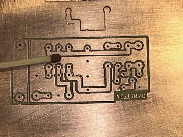
It works well. But one problem is, that C1 won't discharge quickly enough when doing a fast OFF-ON operation.
This problem can be solved by making a voltage divider (R2 and R3). When power is applied, the diode D2 won't affect the charging of C1 (since the cathode is higher than the maximum charged voltage on C1).
But when the amplifier is turned off, the potential on the cathode of D2 will drop and C1 will be quickly discharged by D2 in series with R3.
R2 and R3 is selected to benefit a fast discharge. A fast discharge requires a low R3 and a even lower R2. That much higher requires a high quiescent current. I selected R2=1K and R3=1,2K as a good compromise: 11 mA results in at total power of approx 260 mW (two ordinary 250 mW resistors can be used).
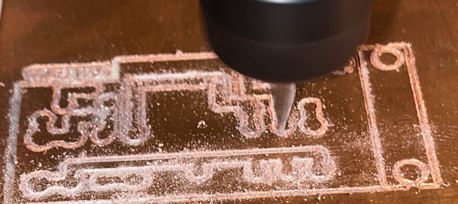 I cutted and drilled the PCB on my "toy-CNC".
 Yes, it needs some final works.
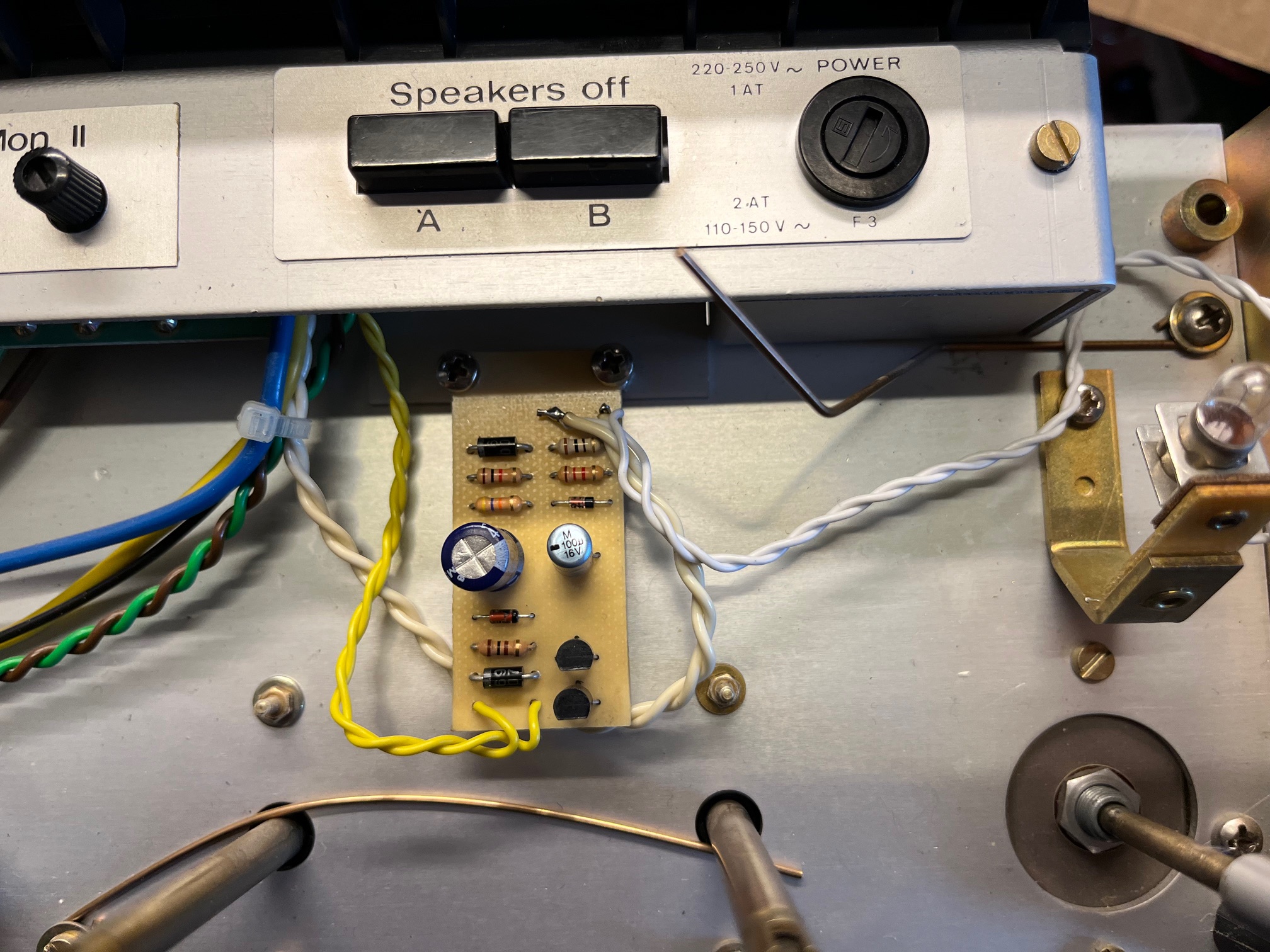 I designed the PCB to be attached directly on the bracket, that holds the speaker swich on my A78.
Here we also have the AC line for lit up the power-lamp. The relay wire goes back to where the speaker cables goes.
I designed the PCB to be attached directly on the bracket, that holds the speaker swich on my A78.
Here we also have the AC line for lit up the power-lamp. The relay wire goes back to where the speaker cables goes.
I like the idea. In a non-destructive way, I was able to remove the frustrating POPS in my speakers. I even found a fiberglass PCB with a color similar to the Revox phenolic crap :)
Circuit, PCB-layout, Gerbers (KiCAD) and FlatCAM G-code can be found here