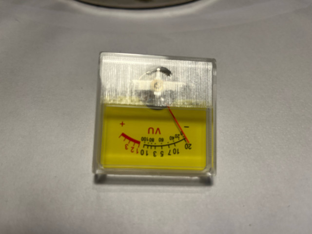
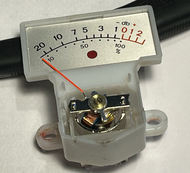
A common issue with old Revox equipment is that the meters get stuck. If you perform an autopsy on these, you'll see that they are built in a very unconventional way, and the problem typically arises when the center magnet (which is glued to the armature) comes loose and does what magnets do: sticks to metal parts. As a result, the moving coil can no longer rotate freely, and the pull can even damage needle bearings, springs, and the windings on the moving coil. Often (with a bit of luck), you can get some glue onto the exposed part of the magnet and carefully rotate the magnet so that its poles are vertical, then pull the magnet back under the armature and center the magnet with a couple of toothpicks as a counterhold. If the poles are swapped, you can just reverse the instrument's terminals; the function remains exactly the same and is associated with less risk than trying to rotate the magnet up to 180 degrees. However, the operation is difficult and always associated with risk, so it's a good idea to continuously check with an ohmmeter to see if the coil is still intact. If the coil wire breaks, the meter is doomed, and there's no point in continuing the project to get the magnet back in place.
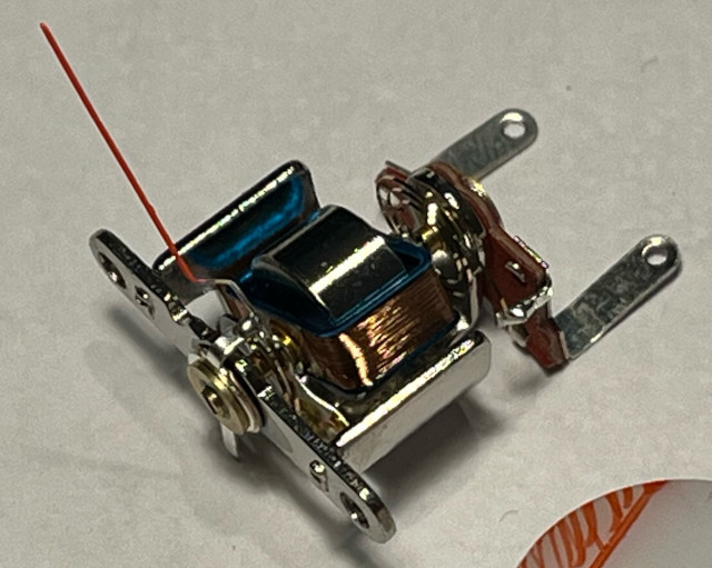
In my case, the coil was damaged. But instead of throwing the meter in the trash, I wanted to try to "transplant" a new meter into the original Revox meter.
I bought a cheap 200uA meter on Ali Express. Outwardly, it's ugly and fits poorly (in my case, in a Revox A77).
 But appearances can be deceiving! Behind the ugly plastic, there is a familiar meter that looks reasonable (better than the original Revox). The meter itself is just pressed into the plastic, so it's not difficult to remove.
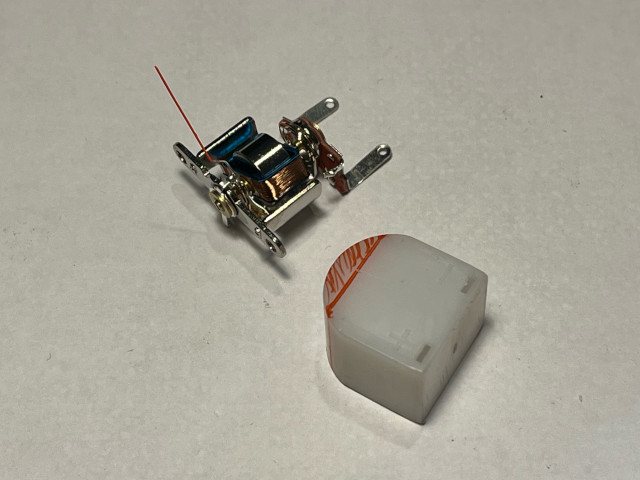
 My plan for the transplantation is to keep only the most necessary plastic on the Chinese meter and remove as little plastic as possible from the original Revox meter, aiming for the ideal situation where the two plastic parts can be glued together. Marked in red shows how little plastic remains from the new meter.
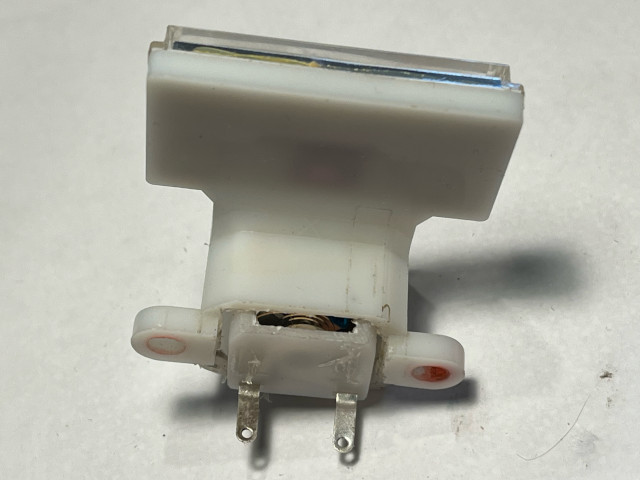
 To make room for the "adapter," unfortunately, the Revox meter has to be cut. The new meter is slightly deeper, so there's no room for it unless the bottom is cut free.
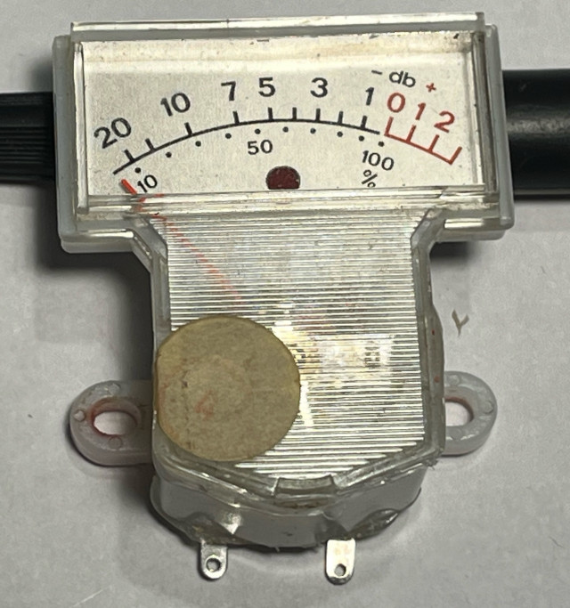
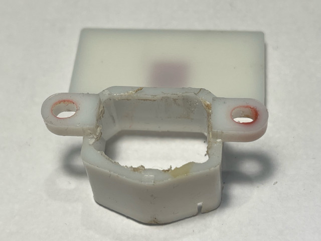 The finished result: The two pieces of plastic can be pressed together and are actually very stable, but a little "sealing" with hot glue does no harm and can seal cracks and protect against dust, metal dust, and thunderflies.
There are not room for the bracket, so I cutted them.
The finished result: The two pieces of plastic can be pressed together and are actually very stable, but a little "sealing" with hot glue does no harm and can seal cracks and protect against dust, metal dust, and thunderflies.
There are not room for the bracket, so I cutted them.
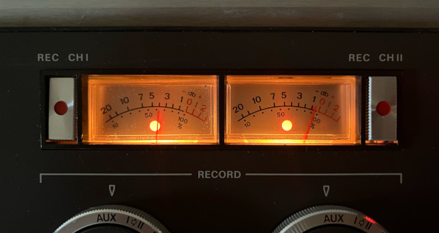
 The meter on the right is the original. You notice that the pointer on the non-original one is a bit shorter, but it's a cumbersome process to lengthen the needle, and it would also require an extra counterweight if the machine is to stand upright (which my A77 does). I think the result is definitely better than a dead meter.
 Since the circuit has to be fast reacting when the amplifier is turned on-off, the circuit has to be coupled to the AC-part (secondary winding) of the mains transformer.
D4 and C2 will make DC-voltage. The ripple is quite high but sufficient to keep the relay switched without buzzing, but fast reacting when the AC-voltage suddenly disappears (when the amplifier is turned off).
No voltage regulation is used, but R1 is used to limit the DC-voltage to +24VDC when the relay is loading the circuit.
The relay is placed outside the circuit. Thats makes it easy to use different footprint and near the speaker connections. D1 is a "Flywheel-diode" to avoid damaging some nearby components sensitive to high voltage when the current flow is interrupted.
The current flow is controlled by a darlington configuration. The high current gain will make the switching more "consequent" when C1 is charged up by the current, limited by R4. R5 is used to limit the base current though the transistors. The zener diode D3 is used to "extend" the delay time (insted of turning on at C1 = 0,7V+0,7V=1,4V, we have to wait until C1 is charged up to 11,4V.
The time constant R4 and C1 is selected long enough so the "POP" can be avoided but short enough to hear when the amplifier is fading in and waking up.
Since the circuit has to be fast reacting when the amplifier is turned on-off, the circuit has to be coupled to the AC-part (secondary winding) of the mains transformer.
D4 and C2 will make DC-voltage. The ripple is quite high but sufficient to keep the relay switched without buzzing, but fast reacting when the AC-voltage suddenly disappears (when the amplifier is turned off).
No voltage regulation is used, but R1 is used to limit the DC-voltage to +24VDC when the relay is loading the circuit.
The relay is placed outside the circuit. Thats makes it easy to use different footprint and near the speaker connections. D1 is a "Flywheel-diode" to avoid damaging some nearby components sensitive to high voltage when the current flow is interrupted.
The current flow is controlled by a darlington configuration. The high current gain will make the switching more "consequent" when C1 is charged up by the current, limited by R4. R5 is used to limit the base current though the transistors. The zener diode D3 is used to "extend" the delay time (insted of turning on at C1 = 0,7V+0,7V=1,4V, we have to wait until C1 is charged up to 11,4V.
The time constant R4 and C1 is selected long enough so the "POP" can be avoided but short enough to hear when the amplifier is fading in and waking up.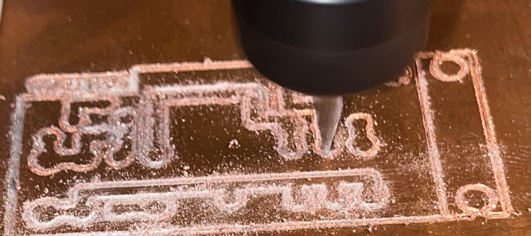 I cutted and drilled the PCB on my "toy-CNC".
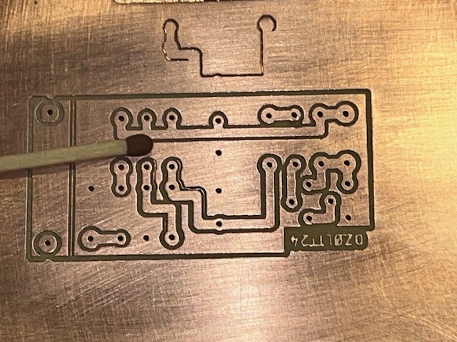 Yes, it needs some final works.
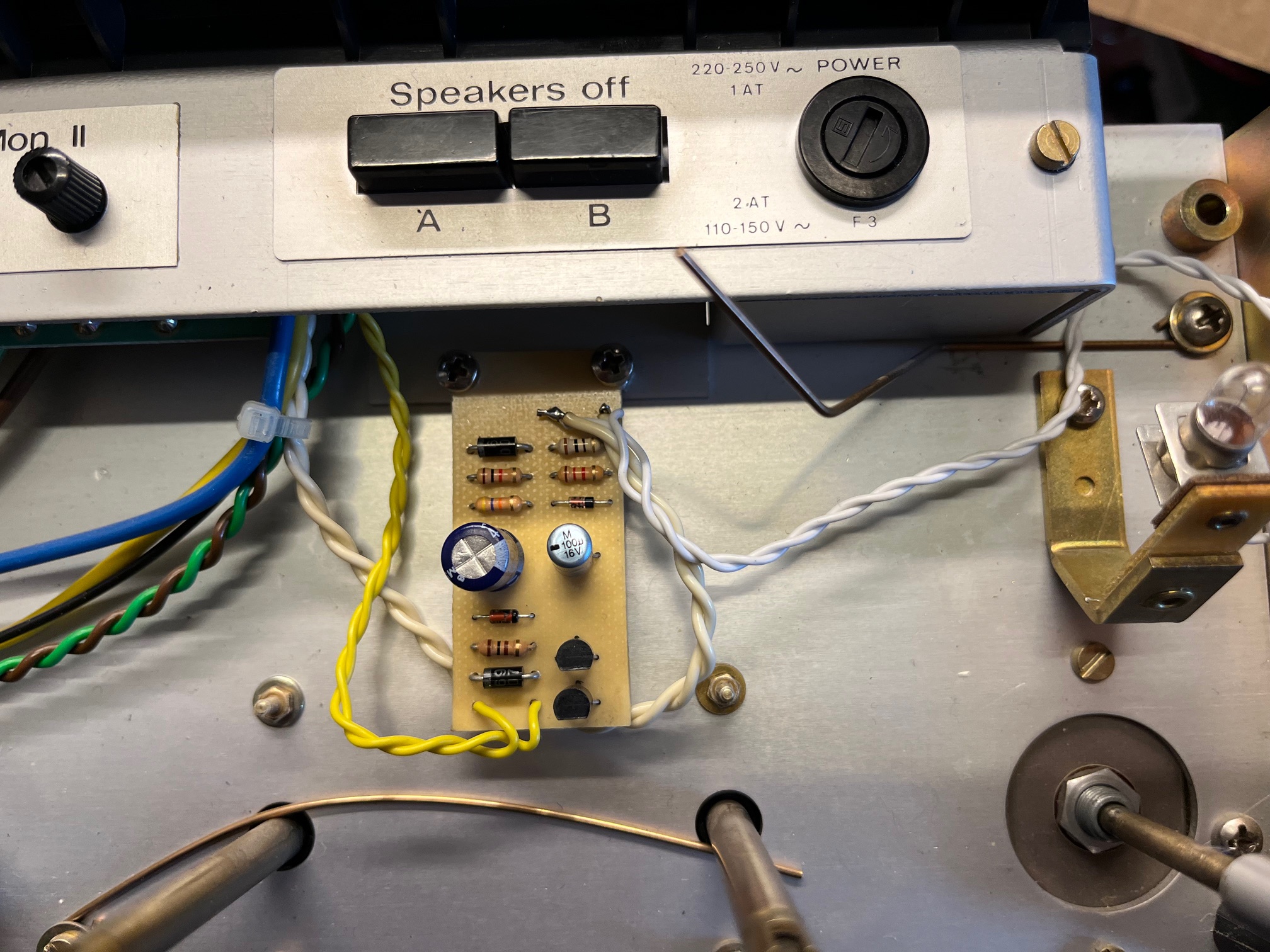 I designed the PCB to be attached directly on the bracket, that holds the speaker swich on my A78.
Here we also have the AC line for lit up the power-lamp. The relay wire goes back to where the speaker cables goes.
I designed the PCB to be attached directly on the bracket, that holds the speaker swich on my A78.
Here we also have the AC line for lit up the power-lamp. The relay wire goes back to where the speaker cables goes.


 In Memory of...